Sizing resistors for diodes and leds is a fundamental skill in electronics design and circuit implementation. Whether you are building a simple indicator circuit or designing a complex lighting system, the resistor value directly affects component longevity, brightness output, and overall circuit reliability. Incorrect sizing can lead to component failure, excessive heat dissipation, or inadequate light output. Understanding the relationship between voltage, current, and resistance is essential for anyone working with semiconductor light emitting devices in any application.
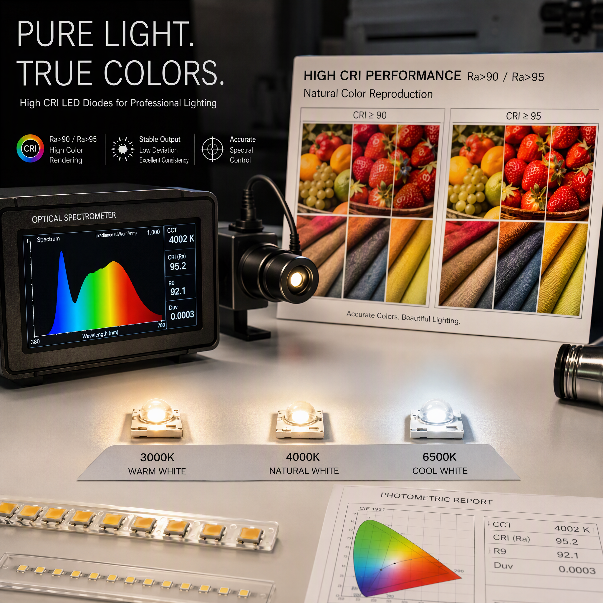
The process of selecting the correct resistor involves calculating the voltage drop across the component and determining the desired current flow. Semiconductor light emitting devices operate within specific current ranges, and exceeding these ranges causes permanent damage. Modern LED efficiency and performance standards demand precise current limiting to maximize brightness while maintaining safe operating conditions. This article walks through the complete methodology for sizing resistors accurately, covering theoretical principles and practical application scenarios across different circuit configurations.
Understanding Voltage Drop and Current Requirements
The fundamental equation for sizing resistors relies on Ohm's Law: V equals I times R. In practical terms, you must first identify three critical parameters: the supply voltage, the forward voltage drop of your semiconductor component, and the desired operating current. The forward voltage drop varies depending on the type of device you are using and its specific material composition. Red LEDs typically have a forward voltage around 2 volts, while blue or white semiconductor light emitting devices may require 3 to 4 volts or higher.
Forward Voltage Specifications
Each semiconductor light emitting device has a datasheet that specifies its forward voltage at a rated current. This specification is crucial because it determines the voltage available for the current-limiting resistor. When you subtract the forward voltage from your supply voltage, the remainder must be dropped across the resistor. Photodiode applications and LED efficiency and performance metrics depend heavily on maintaining the device within its rated operating window. Exceeding the forward voltage tolerance degrades the device quality and shortens its functional lifespan.
Current Rating and LED Efficiency and Performance
The typical operating current for standard LEDs ranges from 10 to 20 milliamps, though some high-brightness semiconductor light emitting devices may require different values. High-power LEDs designed for industrial lighting applications often operate at 350 milliamps or higher, requiring careful thermal management and resistor power rating calculations. LED efficiency and performance improve when the device operates at its designed current level. Undersizing current limits brightness and wastes the component's potential, while oversizing current generates excessive heat and reduces lifespan significantly.
Calculating Resistor Value and Power Rating
Once you have identified the supply voltage and desired current, the resistor calculation becomes straightforward using Ohm's Law. Subtract the forward voltage from the supply voltage to find the voltage drop across the resistor. Then divide that voltage drop by your target current in amperes to determine the resistance value in ohms. For example, with a 5-volt supply, a 2-volt forward voltage LED, and a desired current of 15 milliamps, your calculation would be (5 minus 2) divided by 0.015 equals 200 ohms. Always select the nearest standard resistor value available from manufacturers to simplify procurement and ensure reliable performance.
Power Dissipation in Resistors
Resistors dissipate power according to the formula P equals I squared times R, or alternatively P equals V times I. This power dissipation generates heat that must be managed appropriately. A 200-ohm resistor with 15 milliamps flowing through it dissipates 0.045 watts, which requires at least a 0.125-watt resistor for safety margin. Ignoring power rating calculations leads to resistor burnout and circuit failure. Photodiode applications often involve lower currents and minimal power dissipation, but high-current LED efficiency and performance designs demand careful attention to thermal considerations. Always select resistors with at least double the calculated power dissipation rating to ensure long-term reliability.
Temperature Coefficient and Stability
Resistor values change slightly with temperature, a characteristic defined by the temperature coefficient specification. Carbon film resistors typically have a temperature coefficient of 100 to 500 parts per million per degree Celsius. While this variation is usually acceptable for simple LED circuits, precision photodiode applications and systems requiring stable LED efficiency and performance benefit from lower-coefficient resistors. High-temperature environments or wide operating temperature ranges necessitate metal film resistors with better stability. Always verify that your resistor selection maintains acceptable performance across the full operating temperature range of your application.
Circuit Configuration Considerations
Resistor sizing requirements vary depending on whether you are designing a series circuit or implementing more complex topologies. Series circuits represent the simplest configuration, where a single resistor limits current for one or multiple semiconductor light emitting devices. Each configuration presents different sizing challenges and requires specific attention to voltage distribution and current balance. Understanding these variations ensures optimal LED efficiency and performance across diverse industrial and consumer applications.
Series Circuits with Single Devices
The most common resistor sizing scenario involves a single LED connected in series with a current-limiting resistor to a power supply. This configuration is straightforward and appears in countless applications from indicator lights to simple status displays. The resistor protects the semiconductor light emitting device by preventing excessive current flow. Once you calculate the resistor value using the method described earlier, implementation becomes simple and reliable. This approach works well for low-power applications but becomes inefficient for high-power LED systems requiring significant current draw.
Multiple Devices and Complex Topologies
Parallel configurations of semiconductor light emitting devices require more careful analysis because current divides among the devices based on their forward voltage characteristics. Slight variations in semiconductor light emitting devices cause current imbalance, where some devices draw more current than others. This unequal distribution reduces overall LED efficiency and performance because brighter devices draw more current and age faster. Series-parallel arrays balance these concerns but require additional resistor placement and more complex calculations. Photodiode applications often involve different circuit topologies suited to signal amplification and measurement rather than simple illumination.
FAQ
What happens if I use a resistor value that is too small?
Using a resistor that is too small allows excessive current to flow through your semiconductor light emitting device, causing rapid burnout and permanent damage. The device heats up internally and fails within seconds of power application. Additionally, the resistor itself may burn out from excessive power dissipation. This scenario demonstrates why precise sizing calculations are essential for any application involving diodes and leds. Always verify your calculations and use the standard resistor value closest to your calculated requirement without going lower.
How do photodiode applications differ from LED sizing?
Photodiode applications involve reverse-bias operation and sensitivity to light rather than light emission. Current-limiting resistors serve different functions in photodiode circuits, often working with transimpedance amplifiers rather than simple series configurations. The sizing approach considers signal amplification requirements and noise characteristics instead of brightness output. Understanding this distinction helps engineers select appropriate components for each specific application. While both involve semiconductor light emitting devices in principle, their circuit roles and sizing methodology differ significantly.
Why is LED efficiency and performance affected by resistor sizing?
LED efficiency and performance depend on operating at the rated current specified in the device datasheet. Undersizing resistors risks damaging the device through overcurrent, while oversizing resistors reduces current below the rating, dimming output and wasting the device's potential brightness. Proper resistor sizing ensures the device operates at its design point where efficiency is maximized and lifespan is optimized. This relationship between resistor value and semiconductor light emitting device performance makes sizing calculations critical for any professional installation or circuit design project.
 EN